SLAB CONDUITING
1) Preparation of slab conduiting drawing by electrical contractor.
2) Verification by electrical dept. and approval by Engg dept authorized signatory.
3) Slab conduiting on site as per approved plan.
Accessories for Slab Conduiting
1) PVC Pipes.
2) Junction Boxes (1 Way to 4 Ways)
3) Fan Junction Box
4) Couplers
5) Reducers
6) Bends
7) PVC Cement Solvent
8) Paint
STANDARD SPECIFICATION FOR SLAB CONDUITING
1) Conduiting should be done only after slab re-bars are laid and after fixing of PVC cover.
2) Gap between adjacent conduits should be min. 25mm.
3) Conduits should not pass through RCC Column.
4) Conduit drops should be on wall face only.
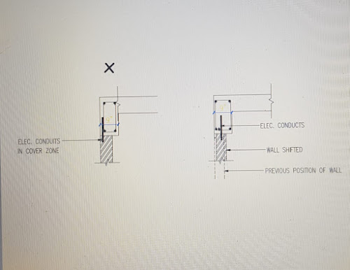
5) Conduits should not be in cover zone of re-bars.
6) Light / Fan points should be painted for easy identification on slab surface soffit (slab shuttering).
7) Conduits & Junction openings to be sealed to avoid choking and should be touching shuttering.
8) Light / Fan / TV / Tel. / Bracket light points should be as per approved electrical layout drawing of slab.
Case Study 1:
In no case; electrical conduits shall be placed in the cover zone. For that, if required, either wall is to be shifted if it is 4” or provide 5” wall as the case may be. The same shall be confirmed by the Site In-charge with respective Project In-charge.
Case Study 2 :
The electrical junction boxes should be clearly touching the shuttering at soffit of slabs and there should not be any gap in between. If the above procedure is not followed; then after deshuttering one has to chip concrete to expose electrical points which is not at all allowed. Hence all are requested to follow below given precautions/ solutions on site to avoid such problems. This will result in breaking of junction boxes while the labours are walking on top of slab.
1- Use additional PVC ring piece in the bottom of the electric box so that elect. boxes are
touching shuttering which is lifted up due to slab reinforcement.
2- As far as possible, lay electrical conduits on main reinforcement instead of distribution
reinforcement so that lifting of conduits is avoided.
3- Make sure that elect. boxes are properly tied with reinforcement so that at the time
of concreting, they are not lifted up due to pressure.
• This is applied only when we are not using deep junction boxes (we are always using deep junction boxes)


Comments
Post a Comment