CAST-IN-SITU BORED PILES
This topic provides basic Guidelines in case of cast in situ piling works, few
points to be taken care of and things which can go wrong on-site during execution.
Cast-in-Situ bored piles, as we all know, are constructed by various techniques:
a) Using permanent casing.
b) Using temporary casing.
c) Using bentonite and chisel bailer boring.
d) Using bentonite with direct mud circulation or reverse mud circulation or
e) The pile may be bored by Rotary method using Rotary piling rigs.
Today, when water is present in the bores, piles are concreted by use of tremmie pipes which is the standard technique and acceptable to all.
In and around the Mumbai area, the average length of piles is generally around 10 metres and most contractors make use of temporary casing of 16 mm thickness driven into the bores upto noncollapsible strata in order to stabilize the bores and prevent collapses. If these casing are driven up to non-collapsible strata and boring is continued at a rapid rate very often, dry bores are possible to achieve.
Under the following circumstances, in dry bores:
1) When bores are less than 12m in-depth,
2) When bore dia. are less than 600mm dia. (small dias.) and
3) When bores do not collapse, the following technique is very effective in constructing piles of
small dias. upto 600mm :
Stage 1: On completing the bore by using temporary casings driven into non-collapsible strata and having achieved a dry bore with no collapse of the sides, the reinforcement steel cage should be cut to size and lowered immediately into the bore. Location of lapping of the reinforcement and staggering of the same or tack welding shall be confirmed from the RCC consultant.
Stage 2: If even 30cms of water has trickled into the bore, it should be bailed out by a water bailer and kept dry.
Stage 3: While the bailing out of water is in process which takes approx. 5 minutes, the concrete of required strength should be kept ready for pouring into the bore.
Stage 4: Also, a concrete ram of 8” dia. made of steel approx. 1.2m to 1.5m in length and weighing approx. 300kgs. should be attached to the wire of the winch and kept ready, after cleaning, for use.
Stage 5: On completion of bailing out of water from the bore, the concrete should be poured into the bore directly from the top. On pouring into the bore approx. 2 or 3 batches/concrete of 2 or 3 cement bags, the ram is lowered into the bore for compaction. The ram is lifted up and down for 4-5 times so that compaction is achieved at the bottom. Further concrete is poured into the bore and is compacted by the ram in the method as above. While the concreting is in progress, a very important operation is to shake manually the reinforcement cage periodically from the top in order to shake off any aggregate pieces that may be suspended in the cage.
Stage 6: It would be advisable to remove the casing simultaneously while concreting is
in progress. This is to ensure that the concrete at the bottom does not set within the casing while the concreting is in progress. If it sets, it forms a plug at the bottom of the casings and lifts the concrete with the cage when the casings are withdrawn.
Stage 7: On completing the concreting of the pile, the ram is kept aside and the last few casings are withdrawn to complete the pile. Records shall be maintained for each pile indicating theoretical and actual consumption of concrete. If the consumption of concrete varies beyond permissible limits (by experience/judgment), then same shall be brought to the notice of engineer in charge.
Caution: This system of concreting should be done with extreme care and should be used only when the bores are dry. It is advantageous to use an extra casing, if required, to seal the bore and make water-tight rather than letting the water have access into the bore. You can beat the ingress of water into the bore by faster speed of work.
Stability of Drilled Shaft
For stabilizing the sides of the bore, following methods can be adopted:
1) For shallow depth upto 8.0 m, temporary casing can be used for the full length of the soil strata.
2) In highly weak or collapsible strata permanent liner can be provided so that the pile shaft is not damaged by side collapse during extraction of liner when the concrete is green.
3) Bentonite suspension of around 6% by weight can effectively support the bore. A positive head of about 1.5 m of bentonite suspension should generally be maintained above the ground water table. Bentonite suspension method is most suitable in sandy deposits.
Concreting of Driven Cast-In-Situ Piles
In Indian practice concreting of cast-in-situ piles is generally carried out by pouring the concrete through the funnel placed on top of mandrel and no tremie is adopted.
Hence, concrete initially generally falls from a height more than length of pile by one or two meters. On its fall path, concrete is very likely to “dance” over the reinforcement. This results in complete segregation of concrete. Such concrete is particularly harmful when it is placed in aggressive ground conditions of high sulphates and chlorides or low pH value, etc.
It is to be realized that such dropping concrete from height more than 2 m is generally not allowed in superstructure and vibrating of concrete is insisted upon.
Though concrete in pile is self leveling concrete with very high slump (150 to 180 mm) such
dropping is to be avoided when vibration of concrete of each pour is not done. Some try to extend the logic that the tamping of mandrel gives vibration. Such tamping does result in very limited vibrations but that is far from adequate. Hence, it is strongly felt that if driven cast-in-situ piling has to continue then existing system of concreting has to be improved greatly for acceptable quality of pile concrete.
Concrete of Cast-in Situ Piles
In pile foundation generally the concrete is required to be placed under water. In such situations tremie method of concreting is generally adopted. It is essential that the concrete to be placed in pile by tremie method has a slump of at least 150 mm. Essential requirement of tremie method of concreting is that tremie pipe should always be well below the water/concrete interface during concreting. However for large diameter piles, tremie pipe even upto 250 mm diameters are being used.
Some Common Construction Problems In Piling
Some of the construction problems which are commonly encountered during execution are listed herein below. These problems along with suggested remedial measures are discussed briefly herein below:
Reinforcement Cage with L Bend at Pile Tip.
Practically all consultants provide ‘L’ bend to the reinforcement cage of the pile at the pile tip (Ref.Fig.)

In the first instant no reinforcement is needed at pile tip to take care of bending moment. Such ‘L’ bending prevents the tremie from reaching the borehole bottom. If tremie does not reach borehole bottom, tremie concreting by displacement method cannot be achieved. Thus, provision of ‘L’ bend prevents good concreting and hence is to be eliminated.
If some designers want ‘L’ bend for the cage for proper resting on pile hole bottom, then
only 4 bars – diagonally opposite to each other – with 3 to 5 cm long ‘L’ bend may be provided on the understanding that tremie can easily pass through the opening to pile bottom.
The method proposed here in eliminating the ‘L’ bend for 4 bars reduces the cost and enables to adopt good concreting practice.
Lowering A Long Reinforcement Cage
In fig. problems encountered in lowering long reinforcement cage in pile bore are
illustrated. As a result of such problems lot of muck/soil gets scrapped while lowering the cage and gets accumulated at pile tip. Hence, it is always recommended procedure, to remove such loose material/muck by mud circulation/compressed air after reinforcement cage is lowered, except when rotary piling equipment is used. When rotary piling equipment is used, pile tip cleaning is done using cleaning bucket just before reinforcement cage in lowered. When such equipment is used, because of long length of Kelly or high capacity crane, it is generally possible to lower the reinforcement cage without scrapping the sides. If sides are scrapped and loose material get collected at pile tip, then it is essential to remove it after lowering the reinforcement by direct/reverse mud circulation or using compressed air.
Necking And Bulging In Soft Clays
When bored piles are installed through bouldery stratum (fill) overlying very soft to soft clay
stratum, there exists some possibility of necking and bulging (refer fig.) In such a case it is desirable to provide permanent or at least temporary liner extending preferably upto bottom of soft clay or at least a metre below bottom of boulders.
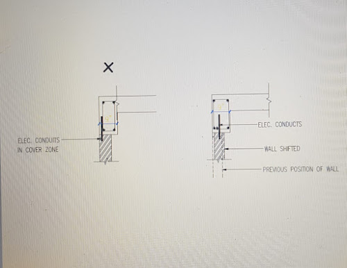
Incorrect Use Of Binding Wire
Generally Mild Steel (MS) binding wires are used in preparation reinforcement cages. Correct way of using the binding wire on reinforcement cage is to see that loose ends project inwords and not outwords (refer fig.). Secondly one should stop using unnecessarily long length of binding wire pieces than necessary. When unbound lengths of binding wire pieces are long and tied projecting outward they may project outside and beyond the concrete cover. Such binding wires are source of corrosion. Even when they do not project out of concrete, if concrete cover is less, the corrosion process would start early on these wires. Hence, it is strongly advised to use correct procedure i.e. ensure loose end of wires project inwards and only necessary lengths of wires are used. M.S. binding wires are most likely to corrode much faster. Hence, use G.I. binding wire.
Poor Quality Concrete Cover Blocks
If concrete cover blocks are used then grade of concrete, W/C ratio, cement type and cement content etc. of these blocks should be same as that of pile concrete and these blocks should be properly compacted. Unfortunately, often concrete cover blocks are cast without giving due consideration to above facts. As a result concrete cover blocks are cast with lower strength grade of concrete, higher W/C ratio, without vibrations / compactions, etc.
Best alternate is to use plastic cover blocks. However, when reinforcement cage is heavy and long, these cover blocks may get broken unless they are made of adequate strengths. Such care needs to be taken.
Poorly Designed Concrete Mix
Under this heading, three aspects of concrete mix are considered viz; grade of concrete, water cement ratio and cement content. In our country, general tendency is to use M-20 grade concrete. BIS allows in IS 2911 Part III (under reamed piles) even M-15 concrete. Since piles are increasingly used in hostile/corrosive subsurface environment and since permeability of concrete is high with low strength concrete, it is desirable to use M-30 and higher grade concrete except for light loaded structures and under non-hostile subsurface environment.
For cast-in-situ piling, one needs very high slump concrete. Slump required is of the
order of 150-180 mm. Hence, general tendency is to use more water. Even BIS permits W/C ratio more than 0.5. however it is to be noted that for durable concrete cement content used and used within the permissible limits, there is no harm using plasticizer.
Many including leading consulting organizations believe it is always better to use more cement. Accordingly, one should use minimum cement content which would give the required strength grade of concrete for given water cement ratio. Hence, it is wrong to specify minimum cement content. Better practice would be to put restriction on maximum cement content.
Few pictures of different operations carried out in case of cast in situ piles.


Comments
Post a Comment